¶ Chalmers Aerospace Society for Advanced Rocketry
This page summarizes the key theory, equations, and reference values used for analyzing rocket propulsion in our designs. All calculations assume idealized isentropic flow conditions. In practice, real performance will be lower due to losses such as friction, non-ideal combustion, temperature loss, and nozzle inefficiencies. Most of the theory is taken from NASA:s offical website.
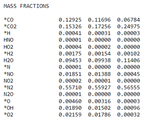
The Cearun website, developed by NASA Glenn Research Center, is an online interface to the Chemical Equilibrium with Applications (CEA) program. Its purpose is to make NASA’s chemical equilibrium code easily accessible through a browser, allowing users to calculate equilibrium compositions, thermodynamic and transport properties of gas mixtures, and performance parameters for propulsion and combustion systems. This tool is widely used in aerospace and combustion engineering for tasks such as rocket engine analysis, detonation studies, and shock-wave calculations, without requiring users to install or run the standalone Fortran-based CEA software.
Isentropic flow describes the ideal expansion of a compressible gas under the assumptions that the process is adiabatic and reversible, so that entropy remains constant. As the gas accelerates, its thermal and pressure energy is converted into kinetic energy, causing velocity to increase while pressure and temperature decrease. To reach the critical velocity of Mach 1, the flow must pass through a convergent section, which accelerates the subsonic gas to the sonic condition at the narrowest point. Beyond this point, further acceleration to supersonic speeds requires a divergent section, where the flow continues to expand and convert pressure into velocity. This idealized model provides a baseline for understanding compressible flow behavior, allowing predictions of velocity, pressure, and temperature distributions without losses from friction, heat transfer, or shocks.
At - throat area Ae - exit area rt - throat radius re - exit radius l - nozzle length α - Nozzle cone angle M - molar mass γ - specific heat ratio Tt - throat temperature Pc - combustion chamber pressure Pe - exit pressure (at the end of the nozzle) Patm - atmospheric pressure m - mass flow rate ve - exit velocity n^ - Surface normal vector
The ignition system consists of a wire that will heat the nitrous oxide gas, causing it to decompose and ignite. This wire will be externally powered by a device similar to a car battery. To determine the wire length and resistance per unit length, you need to calculate the maximum power dissipation:
Pdissipation=πrl(h(Tw−Tg)+ϵσ(Tw4−Tg4))
Where r is the radius of the wire, l is the length of the wire, h is the conductivity of the gas, Tw is the temperature of the wire, Tg is the temperature of the gas, ϵ is the emissivity, and σ is the Boltzmann constant. Note that h is highly dependent on gas mass flow and temperature, so this formula is only accurate for very still gas. The electric power can then be determined where the current flowing through the wire is:
I=ρwl+RlU
Where ρw is the resistance per distance of the wire, Rl is the sum of the internal resistance of the battery and the wire connecting to the heating wire, Rl=Rb+Rwl. The electric power can then be determined with:
Pelectric=ρwl(U−Rlρwl+RlU)2
Where U is the open-circuit voltage of the battery. The resistance of the heating wire will increase as the temperature rises, so it is a self-stabilizing system. However, these powers should be somewhat similar, at least. The dissipated power formula is not always fully accurate, so it should be used more as a guideline. Also note that for small Rl which it should be, Pelectric∝r2 and Pdissipation∝r, meaning that a larger diameter wire allows for higher power heating of the gas but requires a linear increase in length l to compensate for the quadratic increase in power.